
Autonomous Zipline Delivery Vehicle
Autonomous Zipline Delivery Vehicle for a Design-Build Competition
Team Lead / Mechatronics Engineer
Placed the package in Zone D during the live run and finished 1st in the Deakin SEMW200 2022 cohort.
- Arduino Mega
- Autodesk Inventor
- Stepper motors
- FMEA
- Mechanism design
Hardest engineering problem: Open-loop autonomy was only credible because mechanical repeatability, actuator sizing, servo angles, and step counts were tested together.
Overview
This was an autonomous design-build vehicle for a physical scoring task: pick up a package, traverse a steel-cable zipline over a chasm, deposit the package into a scoring zone, and return within a fixed time window. I frame it as an engineering project first because the work was about mechanism tradeoffs, actuator sizing, firmware sequencing, safety analysis, and test-driven reliability under real competition constraints.
My Role
I served as team lead and owned much of the technical execution: Arduino firmware, CAD and mechanism design, force and motor-sizing calculations, FMEA, fabrication planning, and subsystem debugging. The broader team contributed concept alternatives, documentation, presentation work, and build support; my role was to keep the design moving from ambitious mechanism to reliable integrated machine.
Key Results
- Placed the package into Zone D during the live 35th Engineers Australia Warman run.
- Finished 1st in the Deakin SEMW200 2022 cohort.
- Matched the lab baseline of 9 successful Zone D deposits across 10 test runs.
- Completed the full pick-and-place run in about 25 seconds with a 3.3 kg, roughly 85 cm vehicle.
- Recovered time lost to lift-speed underestimation by overlapping lift motion with cable travel.
Project Visuals
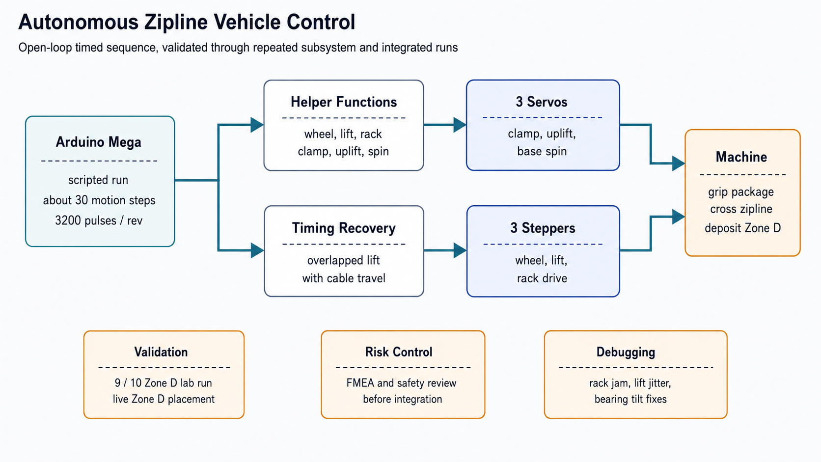
System Architecture
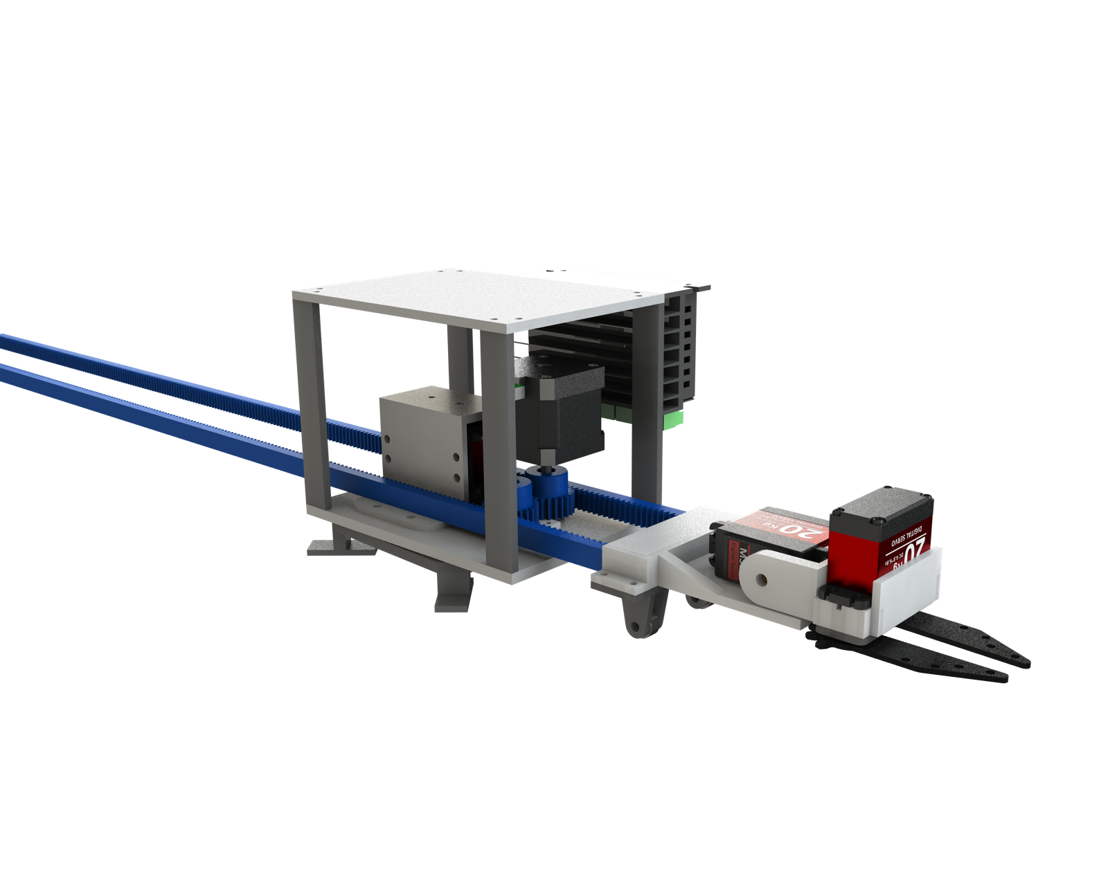
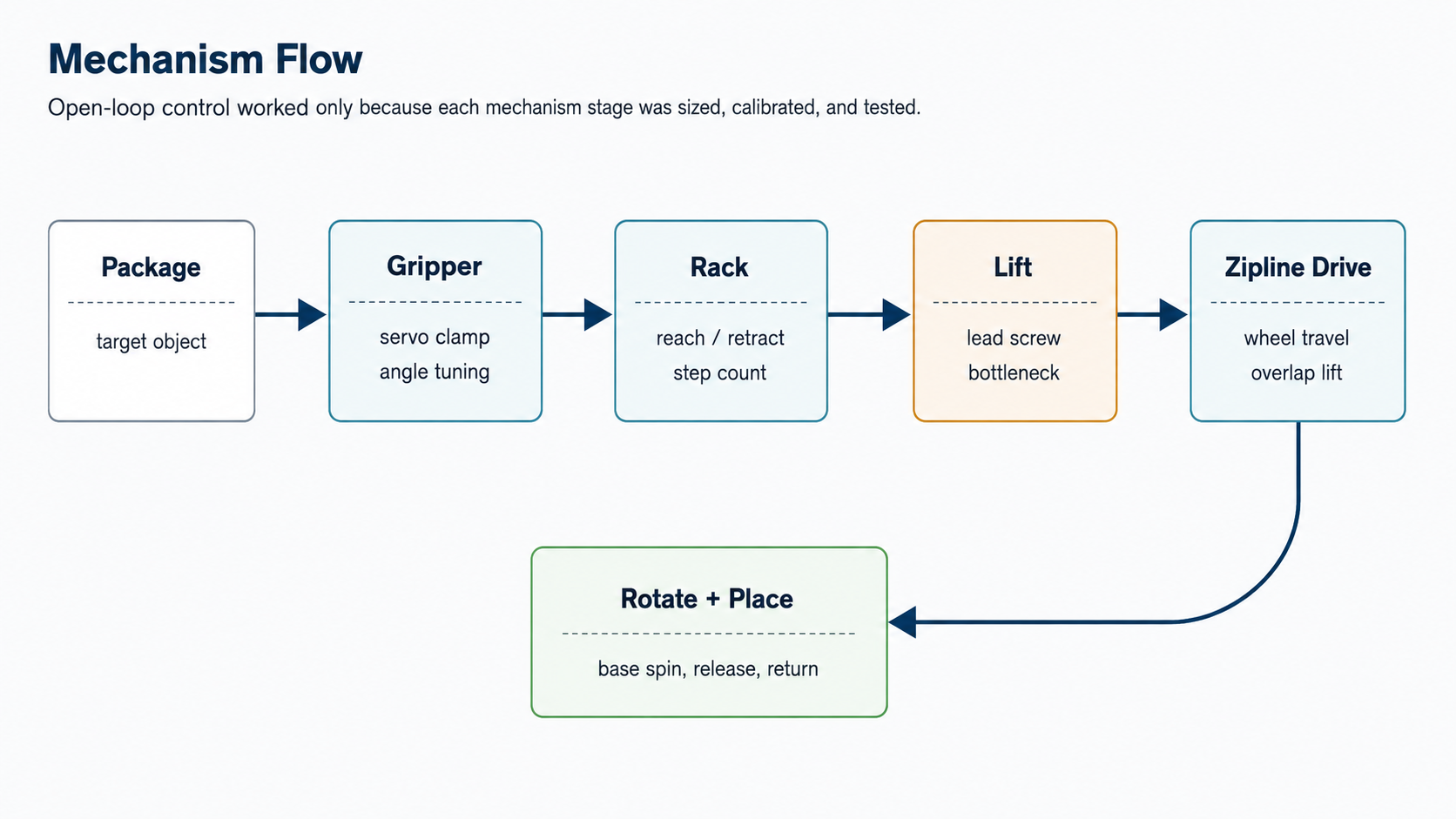
Mechanism
Gripper, rack extension, lift frame, zipline wheel drive, and base rotation worked as one timed package-handling sequence.
Electronics
Arduino Mega controlled three TB6600-driven steppers, three servos, power distribution, and the competition run trigger.
Reliability
Repeatability came from motor sizing, step counts, servo angle calibration, and physical fixes to slip and lift jitter.
Software / Firmware Architecture
| Firmware layer | Function | Reason |
|---|---|---|
| Stepper helpers | Wheel travel, lift, and rack motion using direction, turn count, and pulse timing. | Made each axis testable before the full run was composed. |
| Servo helpers | Clamp, uplift, and base-spin angles with timed incremental motion. | Reduced mechanical shock and made angle tuning explicit. |
| Run script | About 30 timed motion steps for grasp, lift, traverse, rotate, place, and return. | Open-loop control was acceptable only because the mechanism was repeatedly calibrated. |
Control / Simulation Methodology
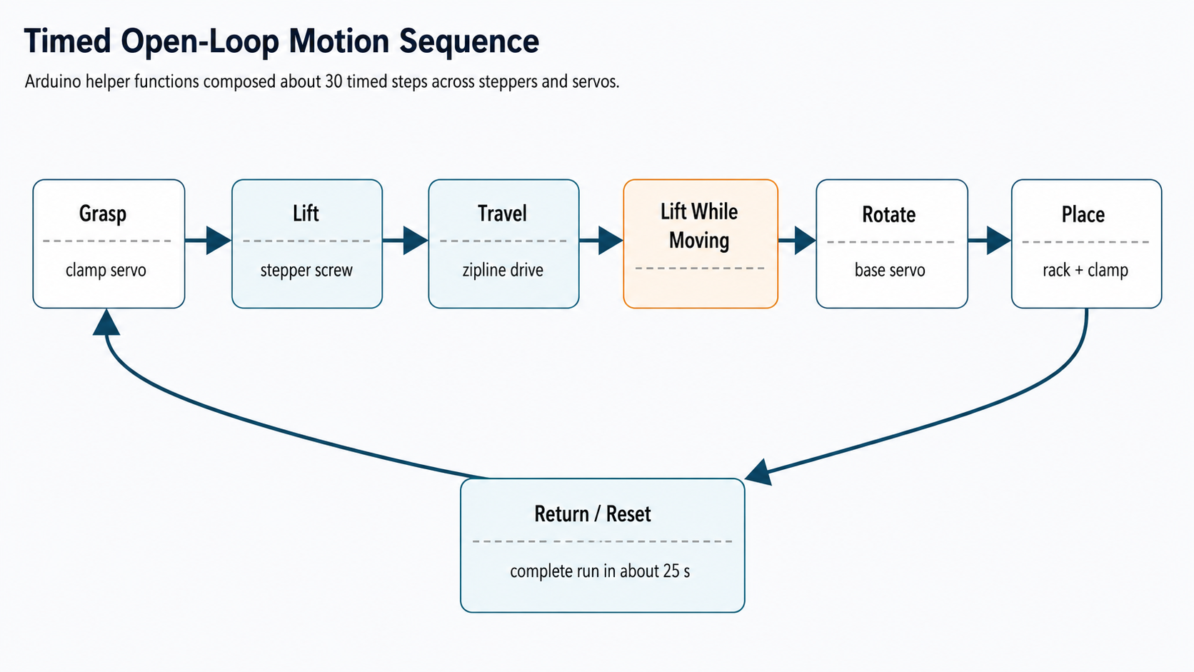
The final sequence was scripted rather than sensor-closed-loop, so mechanical repeatability and timing discipline mattered. I used force analysis and motor sizing before committing to the lift, rack, cable traversal, clamp, and rotation subsystems, then turned those assumptions into step counts, servo angles, and timing delays.
When lift speed became the bottleneck, the recovery was architectural rather than just parameter tuning: instead of fully lifting and then traversing, the vehicle lifted just enough to clear the ground and continued lifting while moving on the cable.
| Open-loop risk | Mitigation | Evidence surfaced publicly |
|---|---|---|
| Stepper travel mismatch | Force sizing, pulse counts, and subsystem calibration before full-run testing. | Three TB6600-driven steppers and helper functions for direction, turns, and pulse timing. |
| Servo shock or angle drift | Incremental servo motion and explicit angle tuning for clamp, uplift, and rotation. | Scripted clamp and base-rotation sequence. |
| Lift timing bottleneck | Overlap lift with cable travel instead of waiting for full lift before traversal. | Final run completed in about 25 seconds. |
Validation & Debugging
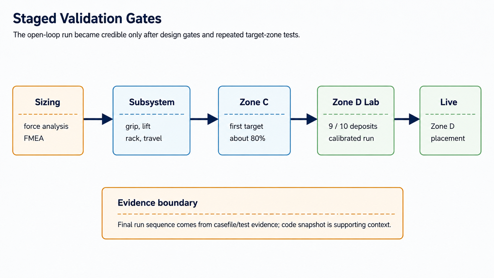
Subsystems were tested before final integration: grasping, lift, base rotation, rack extension, and zipline travel. The final lab baseline reached 9 successful Zone D deposits across 10 test runs, then matched that target in the live competition run.
Validation evidence: the public result combines staged subsystem tests, a 9/10 Zone D lab baseline, and a live Zone D placement during the competition run.
Post-assembly debugging included blocked M3 screw access, rack jamming at the neutral section, under-strength linear bearings causing tilt on drop, and a 2 mm lift-mechanism gap that produced jitter. Each issue was fixed mechanically before the run sequence was trusted.
What I Would Improve
I would add at least minimal state feedback in a next version: limit switches for lift/rack endpoints, a run-state indicator, and logged timestamps for each actuator segment. I would also bring the team into major mechanism choices earlier, because the lead-screw lift decision would likely have benefited from more review before it became a runtime bottleneck.