
Bio-Inspired Lattice Control Surface
Bio-Inspired Lattice Control Surface for Additive Manufacturing
Advised by: Professor Lin Xin
Undergraduate Thesis Researcher
Selected CR2A0/RP2ST2 through modal and compression screening, then validated the structure while identifying why passing a spec is not the same as being optimal.
- LS-DYNA
- HyperMesh
- FEA
- Granta Selector
- CAD
Hardest engineering problem: The research had to narrow a large lattice design space while keeping simulation failures, validation claims, and optimization limits honest.
Overview
This thesis explored how additive manufacturing could make aircraft control-surface skin lighter while still meeting structural requirements. The core design tension was that a streamlined aerodynamic surface constrains the outer shape, while the internal material distribution still needs stiffness, strength, fatigue life, and manufacturability.
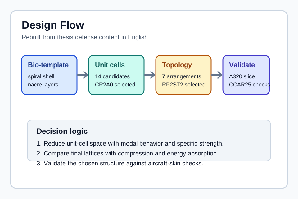
I used a spiral-shell/nacre-inspired lattice as the template, screened unit cells and lattice arrangements, assigned materials with additive manufacturing in mind, then validated the selected control-surface skin model through simulation.
My Role
I was the single named undergraduate thesis author, with advisor review and sign-off from Professor Lin Xin. I owned the major design decisions: the bio-template, the unit-cell family, the final lattice topology, and the aircraft/control-surface validation model.
Key Results
- Screened 14 candidate spiral-shell unit cells and selected CR2A0 with first-order base frequency of 5549.5 Hz and specific strength K = 1.096.
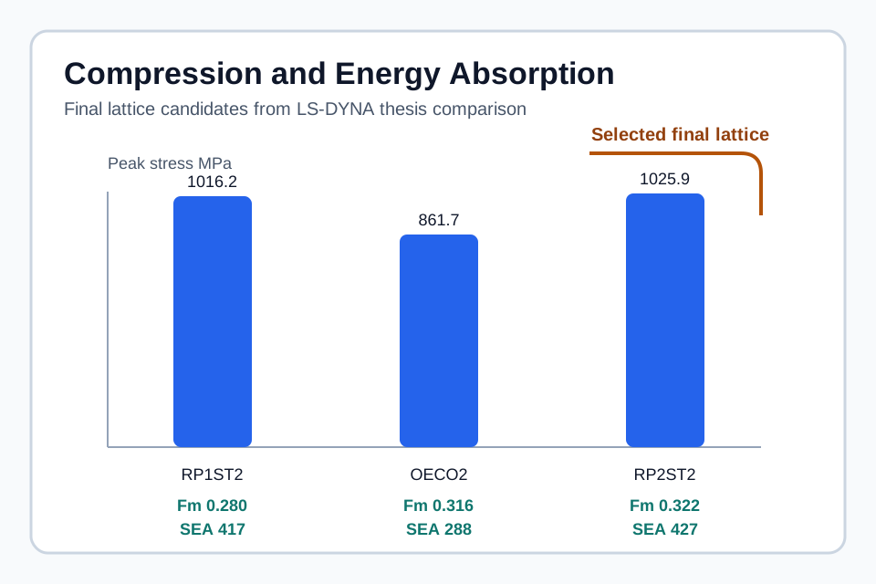
- Built seven lattice topology candidates from transverse arrangements and stagger angles, then selected RP2ST2 using compression and energy-absorption metrics.
- Recorded RP2ST2 as the strongest finalist in the thesis comparison, with peak compression stress of 1025.9 MPa, Fm = 0.322, and SEA = 427.
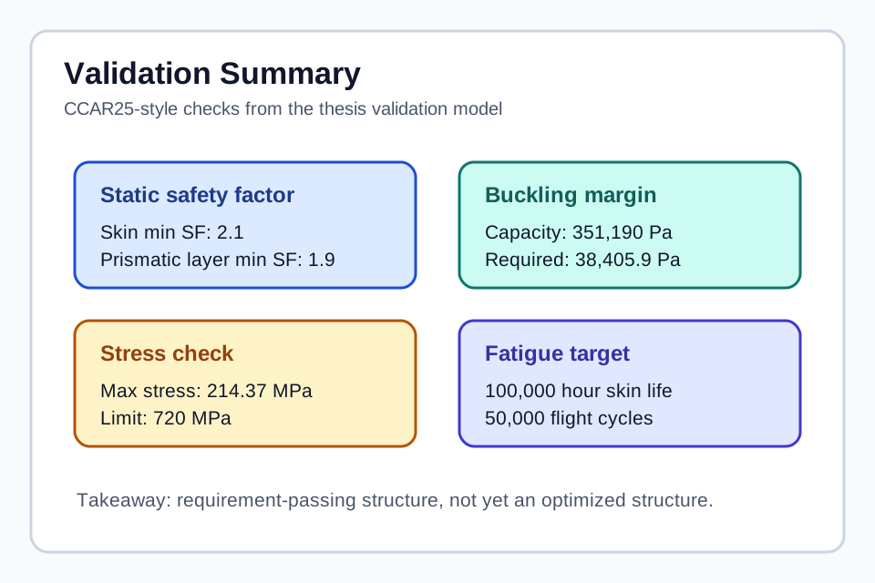
- Validated the selected design against CCAR25-style checks, including minimum safety factors of 2.1 for skin and 1.9 for the prismatic layer.
- Identified the next research gap: meeting the standard does not prove the design is weight, cost, or topology optimal.
Research Visuals
System Architecture
Design Space
Spiral-shell inspiration, 14 unit cells, seven topology candidates, and two AM-suitable material families.
Simulation Stack
ANSYS modal screening, LS-DYNA compression, HyperMesh repair, and FSI-derived control-surface loads.
Validation Context
A320 wing-slice geometry grounded the lattice in a realistic control-surface skin problem.
Software / Firmware Architecture
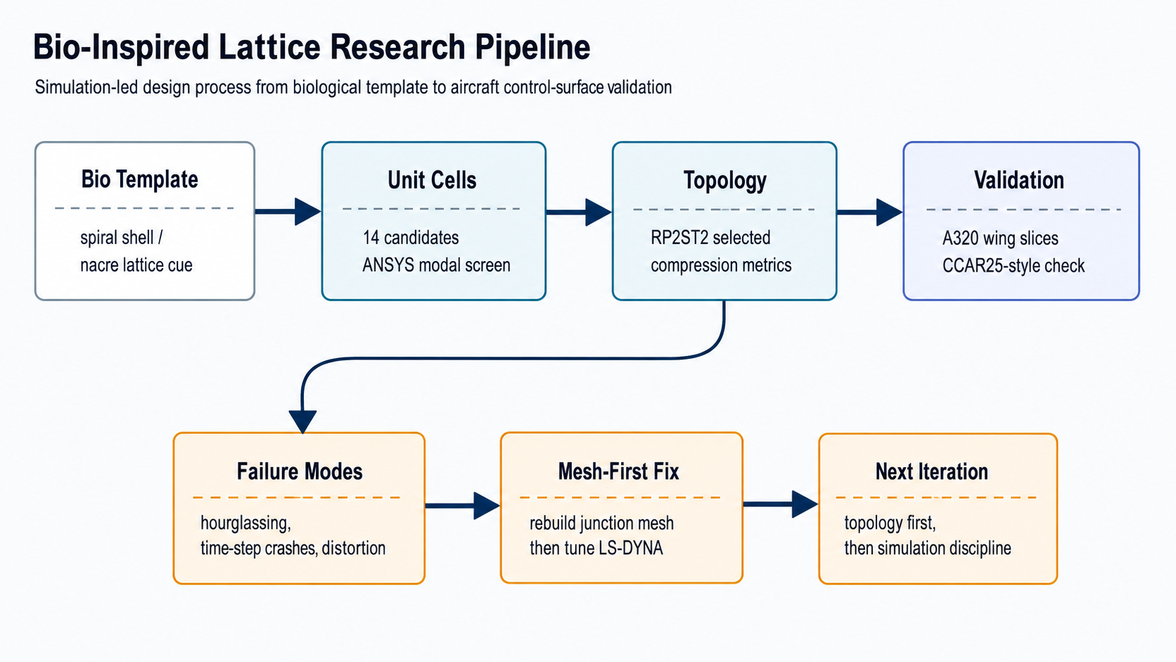
This research page does not have firmware, so the public architecture is a simulation workflow rather than a code stack. The key is traceability: each simulation stage had a different purpose, and the final result should be read as a screened candidate that passed validation, not as a globally optimal lattice.
Flow boundary: this is a thesis simulation workflow, not firmware, certification, or proof of production readiness.
Control / Simulation Methodology
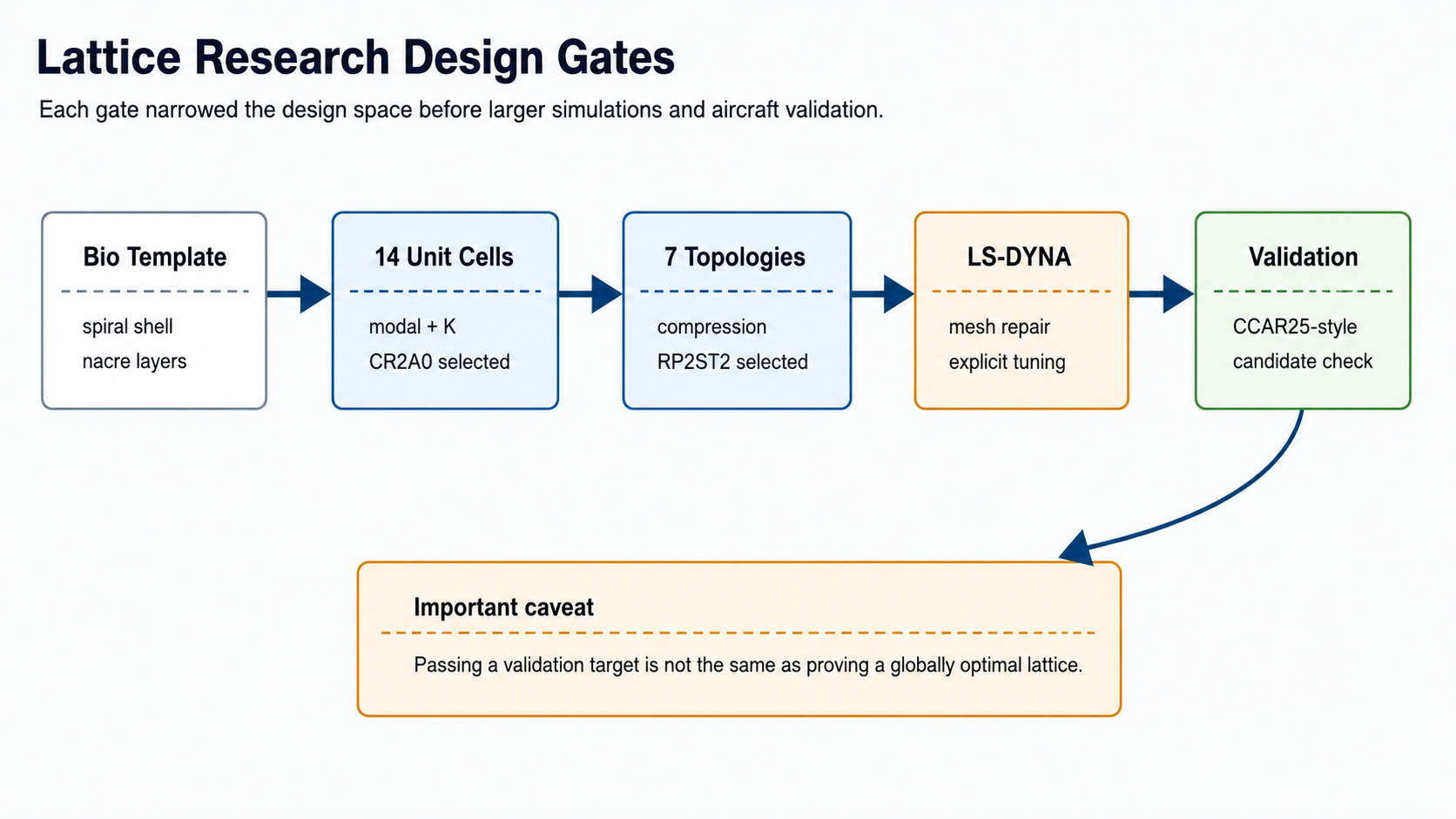
The early work was design-space reduction. I started from shell mechanics and nacre-like layered geometry, created candidate unit cells, then used modal and specific-strength screening to choose CR2A0 before building larger lattice arrangements. RP2ST2 became the final lattice because it performed best across the selected compression and energy-absorption metrics.
| Stage | Tool / method | Decision produced |
|---|---|---|
| Unit-cell screen | Modal analysis and specific-strength comparison. | Selected CR2A0. |
| Topology screen | Compression and energy-absorption metrics. | Selected RP2ST2. |
| Aircraft validation | Control-surface loads and structural checks. | Confirmed the candidate passed the thesis validation target. |
Validation & Debugging
The hardest technical loop was LS-DYNA compression simulation. The spiral-shell topology created contact and large-deformation behavior that triggered hourglassing, time-step crashes, and element distortion. I treated this as a mesh problem first: rebuilding the prismatic-layer junctions in HyperMesh with cleaner elements fixed the geometric source of the worst failures. After that, load ramping, time-step control, and limited stabilization/mass-scaling handled the remaining explicit-dynamics stability issues.
Validation caveat: a passing CCAR25-style check validates a candidate against the thesis target, but it does not prove topology, material, or weight optimality.
Iteration loop: validation and debugging findings should feed the next research cycle: topology first, simulation discipline second, then material and weight optimization.
What I Would Improve
If I continued this line, I would revisit topology first, tighten simulation discipline second with convergence studies and analytical sanity checks, and only then optimize material and weight. Topology sets the ceiling; simulation quality determines whether the comparison is trustworthy.