
LIFT Hybrid Flying-Driving Robot
LIFT: Hybrid Flying-Driving Robot for Hazardous Environments
Team: Eric Pham Felix Hu Jeremy Chen Junyu Lu Max Freeman Show all
Advised by: Professor Francesco Borrelli and Fionna Kopp
Robotics Engineer / Team Lead
Delivered bidirectional ground-flight transformation, closed-loop MPC ground autonomy, and stable hover after post-report tuning.
- SolidWorks
- Ansys
- ROS2
- MPC
- OptiTrack
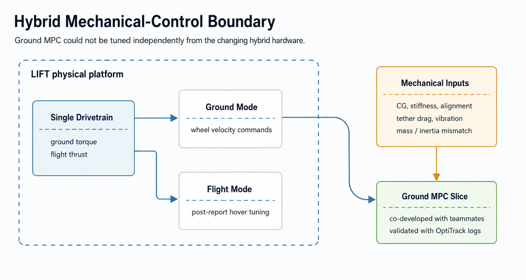
Hardest engineering problem: The controller could not be tuned independently because center of gravity, stiffness, joint alignment, vibration, and tether drag all changed the real hardware response.
Overview
LIFT is a hybrid robotic platform for hazardous-environment exploration, where a pure drone has limited endurance and a pure ground robot cannot cross gaps, rubble, or stairs. The project targeted a simpler single-drivetrain architecture instead of separate ground and flight drivetrains, trading some mode-specific optimization for lower complexity, lower weight, and easier field repair.
My Role
I led the 5-person cross-functional team and owned the mechanical side end-to-end: concept selection, frame design, FEA, 3D-printed fabrication, component selection, packaging, and test arrangement. I also co-developed the MPC controller with two teammates and coordinated milestones, decision matrices, and weekly reviews.
Key Results
- Built a functional hybrid prototype in a 10-week sprint inside a 9-month capstone timeline.
- Delivered bidirectional UAV-to-GAV and GAV-to-UAV transformation, with ground and flight modes independently functional.
- Reduced frame mass by 17% while maintaining factor of safety above 2.0 in high-stress regions.
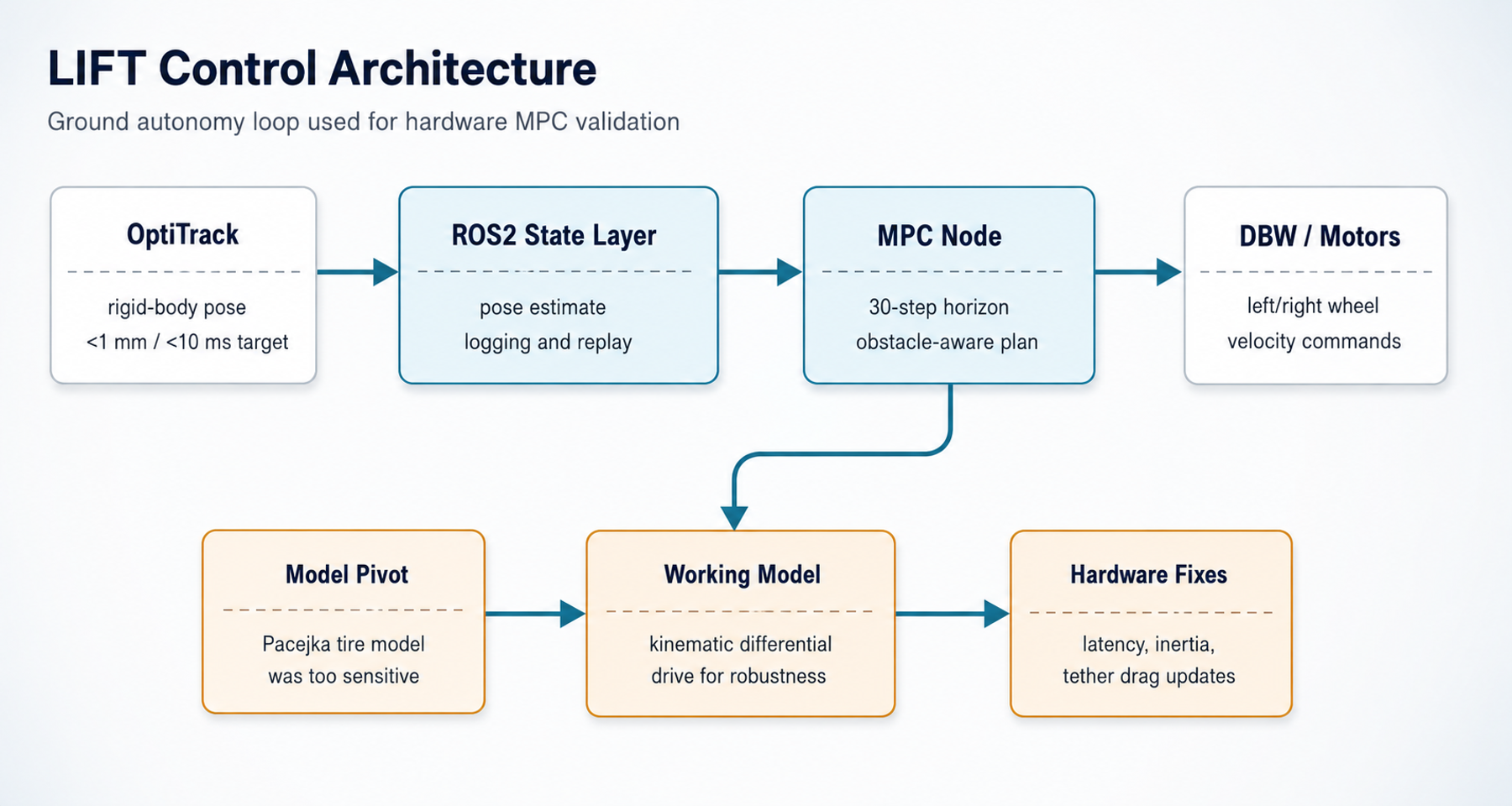
- Integrated OptiTrack pose feedback into the ROS pipeline for closed-loop ground-mode MPC testing on hardware.
- Continued flight tuning after report submission until the platform reached stable hover with joystick forward/backward control.
3D Model Overview
System Architecture
Mechanical Platform
Single-drivetrain hybrid frame, 3D-printed packaging, foldable transformation arms, and thrust-tested motor/propeller selection.
State Feedback
OptiTrack rigid-body pose fed the ROS2 state layer for hardware MPC testing and trajectory logging.
Actuation
Ground-mode commands were reduced to left/right wheel velocities, while flight tuning stayed as a separate post-report push.
Software / Firmware Architecture
| Layer | Public-safe role | Engineering reason |
|---|---|---|
| ROS2 launch/config | Started camera/IMU/GPS/state-estimation components for experiment runs. | Kept sensor bring-up and controller experiments repeatable. |
| MPC node | Subscribed to vehicle state and published scaled wheel-velocity actuation. | Separated high-level planning from drive-by-wire actuation. |
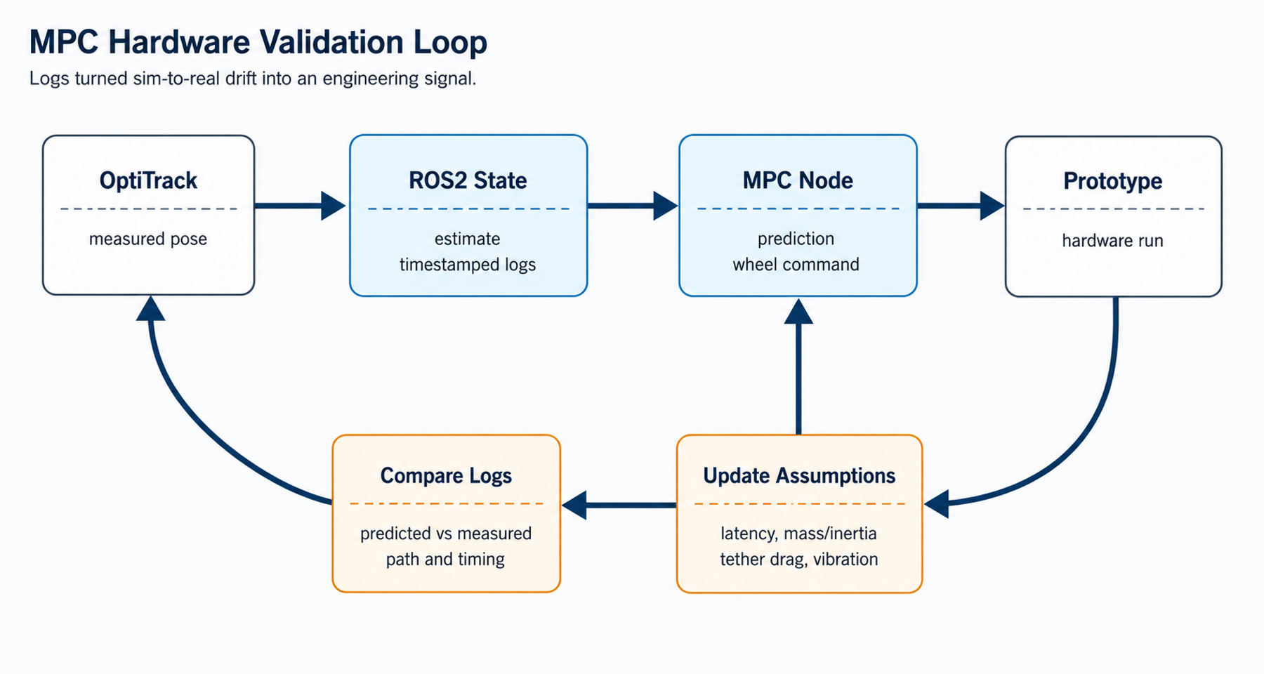
| Logging | Captured predicted trajectory, measured state, and control input traces. | Made sim-to-real drift inspectable instead of anecdotal. |
Control / Simulation Methodology
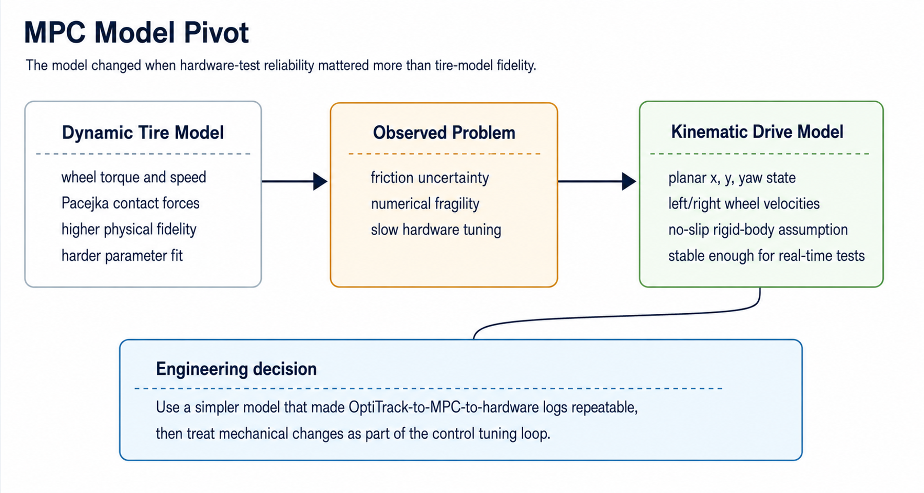
The control stack started ambitious: a higher-fidelity dynamic model with wheel torques and Pacejka tire contact forces. That model was sensitive to uncertain friction parameters and numerically fragile, so the team pivoted to a kinematic differential-drive model with planar-motion, no-slip, and rigid-body assumptions. It was less physically complete, but it was stable enough to run in real time and became the hardware validation model.
| Model choice | Why it was attractive | Why it changed |
|---|---|---|
| Dynamic tire model | Represented wheel torque, angular velocity, and tire-ground contact forces more directly. | Friction and Pacejka parameters were uncertain, making the controller fragile for real-time testing. |
| Kinematic differential-drive model | Used simpler planar, no-slip, rigid-body assumptions that could run predictably. | Less physically complete, but easier to validate and tune on the changing prototype. |
This was not just a software decision. Center of gravity, joint stiffness, frame alignment, and tether drag changed controller behavior, so mechanical and control work had to move together rather than as a handoff.
Ownership boundary: I led mechanical design and team planning, while the MPC implementation was co-developed with two teammates.
Validation & Debugging
The main failure pattern was a sim-to-real gap: the controller reached goals in simulation but ran slower and less cleanly on hardware. We debugged it through repeated hardware-in-the-loop obstacle-course tests, then adjusted the prediction latency, mass/inertia assumptions, and tether-drag model together.
The engineering lesson was that no single parameter explained the failure. Latency, inertia, tether drag, and mechanical vibration were all moderate contributors.
What I Would Improve
For a v2, I would freeze the mechanical platform earlier: center of gravity, stiffness, joint alignment, and wiring layout should be stable before serious MPC tuning begins. I would also separate the ground-autonomy and flight-control validation gates more clearly, so each mode can mature without one unfinished subsystem obscuring the other.